
Firmware for a motor controller is some of the hardest embedded code to test automatically. An ESC (electronic speed controller) only does its real work with a motor attached: it measures phase currents, estimates rotor position from back-EMF, closes a current loop at tens of kilohertz and reacts when the load changes. Take the motor away and most of that code never runs.
Putting a real motor on a CI bench works for a while. Then a propeller needs a guard, the motor needs a load to push against, the battery needs charging, and a firmware bug that shorts a phase takes out a FET at 3 a.m. with nobody in the room. Reproducing "motor stalls at half throttle on a sagging 4S pack" on every commit is not realistic with spinning hardware.
So we are building a board that plays both parts: the motor and the battery. The full hardware write-up is on Hackaday.io. This article stays at a higher level: what a motor emulator has to do, and how it fits into CI.
What a motor looks like from the ESC
To the ESC, a motor is three things per phase:
- Inductance, which sets how fast the current rises during each PWM pulse and how much ripple the current sensors see.
- Resistance, which turns current into heat and voltage drop.
- Back-EMF, a voltage the spinning magnets induce in the windings. It grows with speed and its shape tells a sensorless ESC where the rotor is.
The mechanics sit behind the back-EMF. Torque comes from current, the rotor has inertia, and the load (a propeller, a wheel, a pump) pushes back. The speed that results sets the next back-EMF.
A motor emulator has to reproduce all of that at the ESC's terminals, at full power, fast enough that the ESC's own control loops cannot tell the difference.
How the emulator does it
The idea is simple: keep the part of the motor that is easy to build, and emulate the part that moves.
- Real inductors stand in for the windings. The ESC drives its phases into physical inductors, so its PWM, current ripple and current sensing all behave as they would on a motor. Each phase has a plug-in socket for extra inductance, so the total can match the motor you ship with.
- A second power stage plays the back-EMF. Behind the inductors sits a three-phase bridge that the emulator controls. It switches at 200 kHz and produces the voltage a spinning rotor would.
- An FPGA runs the motor model. It measures the phase currents, computes torque, speed and rotor angle from a model of the motor and its load, and sets the next back-EMF. It also generates the hall, ABZ encoder or SPI encoder signals a sensored ESC expects.
- Protection lives in hardware. Over-current and over-temperature trips latch without any help from the FPGA, so a buggy model or a buggy ESC cannot turn a test into a fire.
The result, in simulation, is that the ESC cannot tell the two apart. The graph below is the same field-oriented ESC driving a real 100 µH motor and the emulator: the phase currents overlap, down to the PWM ripple, and the ESC has to output the same voltage in both cases.
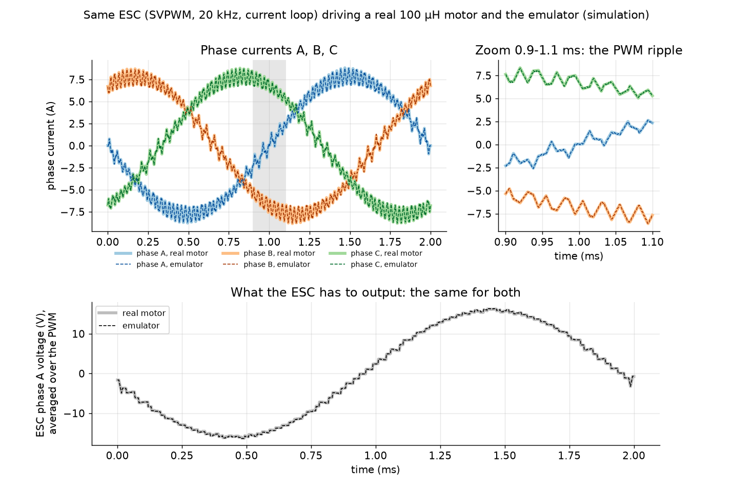
Getting there took more than a model. The ESC and the emulator share one supply, which lets current flow that a real motor's floating star point never would. Six-step ESCs pull their common mode toward ground, where the emulator cannot follow. And the emulator's own dead time costs enough voltage to halve the current. Each of those needed a fix in hardware or gateware, and the Hackaday project walks through them.
The battery comes from the solar simulator
A motor emulator still needs a battery behind the ESC, and a bench supply is a poor one. A real pack sags under load, recovers when the load drops, and gets lower as it discharges. Those are exactly the conditions where ESC firmware has to cut throttle, warn the pilot or shut down cleanly.
We already had a board that does this job: the solar panel simulator. It is a power stage whose output follows a curve the BenchPod computes in real time. Give it a solar I-V curve and it behaves like a panel. Give it a battery model (open-circuit voltage by state of charge, plus internal resistance) and it behaves like a pack, sagging when the ESC pulls current and drifting down as the test drains it.
The emulator board takes that supply through an ideal diode and a hot-swap controller, and adds a brake chopper that can pull the bus down quickly for sag events. The board is rated for 2S to 13S packs. The current solar board tops out at 45 V, so that is the limit for now.
There is a nice side effect. The ESC and the emulator sit on the same bus, so the power the ESC pushes into the "motor" flows back to the bus instead of being burned in a load. The supply only covers the losses, a fraction of the modeled power.
No moving parts
Put together, the bench is:
- the ESC under test
- the motor emulator board, plugged into its phase outputs
- the solar simulator board, playing the battery
- a BenchPod, which loads the emulator's FPGA, sets the motor and battery models, and talks to the ESC
Nothing spins. There is no propeller to guard, no pack to charge and no motor to wear out. The test can run unattended, at night, on every commit.
How it fits into CI
Because every part of the bench is programmable, an ESC test looks like any other BenchPod test. A pytest run can:
- flash the new ESC firmware
- set the motor (pole pairs, inductance, resistance, back-EMF constant, inertia) and the load
- set the battery (cell count, state of charge, internal resistance)
- command a throttle step over the ESC's own interface, such as DShot, PWM, UART or CAN
- read the emulated speed, phase currents and bus voltage back, and assert on them
That makes tests like these routine:
- Start-up: does the ESC spin up a heavy propeller from standstill without desyncing?
- Stall: lock the rotor in the model. Does the firmware detect it and cut current in time?
- Low battery: discharge the emulated pack mid-flight. Does it limit throttle before the cells reach their cutoff voltage?
- Sag: drop the bus by a few volts for 50 ms. Does the current loop ride through, or trip?
- Motor swap: run the same firmware against three different motor models. Does the tuning hold for all of them?
- Regressions: does firmware that passed last month still produce the same currents today?
Each test is the same every time, with numbers you can compare across commits. A real motor on a bench gives you none of that.
Where it stands
The design is parts-picked, reviewed and simulated in ngspice, and the board is heading into layout. The Hackaday project has the details and the simulation results: Motor & Battery Emulator on Hackaday.io. We will write up the bench results when the first boards are running.