
5 V logic
This is the one page about 5 V on the BenchPod: the 5 V I/O mode of the digital board v3r4, and a level shifter for every other board.
RS-485 and Modbus RTU, parity and stop bits and other UART options are on UART devices and RS-485.
5 V I/O (digital board v3r4)
Set the I/O voltage to 5 V: set_la_voltage(5.0) in the SDK and the MCP, benchpod la voltage 5V, la_mv: 5000 in the wiring profile, or {"cmd":"la_voltage","mv":5000}. Every other board refuses 5 V, as before.
- What changes. The LA bank and the FPGA stay at 3.3 V. Clamps on the LA lines keep 5 V off the FPGA. J1 pin 21, the rail every pull-up pulls to, goes to 5 V from the pod's USB supply.
- Inputs. The LA lines are designed to take 5 V signals and read them at full speed on all 14 channels (not measured yet).
- Outputs. A pod output drives a 3.3 V high. It reaches 5 V only through its pull-up, so switch the pull-up on for an output into a 5 V CMOS-level input. The pod picks 2.2k for outputs in 5 V mode. TTL-level inputs (HCT logic, many RS-485 transceivers) are specified to take a 3.3 V high without the pull-up. A pull-up makes the rising edge slower than the falling one: see 5 V speed limits.
- The check. After switching, the pod measures pin 21. Below 4.3 V (a weak USB supply) it goes back to the previous voltage and refuses with
BP0028. - Back to 1.8 V or 3.3 V. Pin 21 follows the bank again. The pulls stay as they were. After any bank change the pod waits 30 ms (calculated) before it drives.
benchpod.set_la_voltage(5.0)        # digital board v3r4 only; BP0028 if 5 V did not come up
v = benchpod.la_voltage()
print(v.voltage, v.pin21.state)     # 5.0 ok
benchpod.set_pull(4, "up")          # an output into a 5 V CMOS input: the pull-up lifts it to 5 V
Pin 21's state is in the la_voltage reply (vref_out), in LaVoltage.pin21 in the SDK, in the MCP set_la_voltage result, and on the benchpod la voltage line. On every I/O voltage, not only 5 V:
| State | Means | What to do |
|---|---|---|
ok | Pin 21 is within the band of its setting (5 V mode: 4.3 to 5.3 V). | Nothing. |
high | More than 0.2 V above its setting: a DUT signal above the I/O voltage lifts pin 21 through the pull resistors. | Select 5 V, or remove the signal. |
low | More than 0.3 V below its setting: something on pin 21 draws too much current. | Remove the load from pin 21. |
short | Under half its setting: pin 21 is shorted or held down. Every pull resistor is off until it is back. | Find the short. |
How the pod picks the v3r4 pull resistors (10k, 2.2k or both, up or down on every channel): Pull resistors. Every field and error is in the firmware's API reference.
5 V speed limits (digital board v3r4)
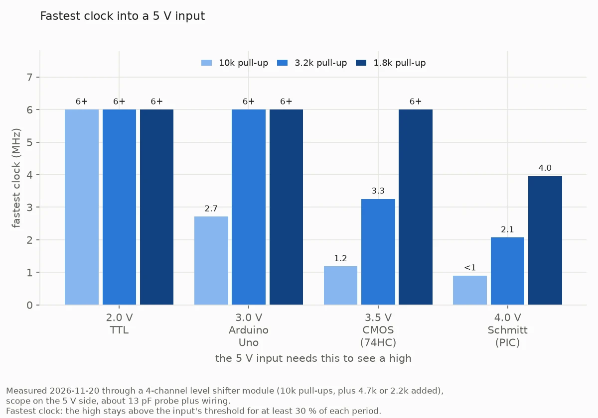
In 5 V mode a pod output reaches 5 V through its pull-up, so how fast it can switch depends on the pull-up and on the voltage your input needs to see a high. Falling edges are fast; rising edges set the limit.
| Your 5 V input needs | For example | 10k | 2.2k (default for outputs) | 10k and 2.2k |
|---|---|---|---|---|
| 2.0 V (TTL) | 74HCT logic, RS-485 transceivers, relay driver boards | 6 MHz | 6 MHz | 6 MHz |
| 3.0 V | Arduino Uno, Nano and Mega | 2.7 MHz | 6 MHz | 6 MHz |
| 3.5 V (CMOS) | 74HC595 shift registers, WS2812B LEDs, 5 V I2C chips | 1.2 MHz | about 4 MHz | 6 MHz |
| 4.0 V (Schmitt) | Schmitt-trigger pins of PIC microcontrollers | under 1 MHz | about 3 MHz | 4 MHz |
| I2C bus | Any 5 V I2C device | 100 kHz | 400 kHz and 1 MHz | 400 kHz and 1 MHz |
The fastest clock at which the high lasts at least 30 % of the period; 6 MHz is the pod's fastest SPI clock. Measured with the same pull-ups through a level shifter module on today's board, which passes less of the edge than the v3r4 circuit, so these are worst case. 2.2k alone lies between two measured values. They will be measured again on the first v3r4 boards.
Works with the defaults
- UART at any common baud rate, into 5 V serial ports and RS-485 transceivers
- I2C at 100 and 400 kHz
- Arduino Uno, Nano and Mega inputs, buttons, enable and reset lines
- SPI into a 74HC595 up to a few MHz, WS2812B LEDs (800 kHz)
Check your device
Look up VIH (input high voltage) in the datasheet of the chip your signal goes into; for I2C, of every device on the bus. At 5 V, "0.7 VCC" is 3.5 V, "0.6 VCC" is 3.0 V, and a TTL input is 2.0 V. Then find your clock in the table, or the voltage in the rising-edge and I2C graphs. Faster than this, or a load that needs current from a high (LEDs, relays): use an external level shifter or a driver.
The LA pins' limit
On boards before the digital v3r4, LA1 to LA14 swing between 0 V and the I/O voltage you set, 1.8 V or 3.3 V, and that is also the most they take: never connect a signal above the I/O voltage you set, so never more than 3.3 V (on v3r4, 5 V I/O takes 5 V). A 5 V signal on an LA pin can damage the pod. See Safety and limits for every port.
5 V TTL serial
Put a level shifter module between the pod and a 5 V UART: its low side on the pod (VCC from J1 pin 17, +3V3, with the I/O voltage set to 3.3 V), its high side on the DUT's 5 V. Use a shifter that is fast enough for your baud rate; most are fine up to 115200 baud.
- DUT TX (5 V) to the high side, low side to the pod's RX pin (LA5 in the examples).
- Pod TX pin (LA4) to the low side, high side to the DUT's RX.
- Pod GND (J1 pin 15) to the DUT's GND.
# The pod's side of the shifter at 3.3 V, the DUT's side at 5 V.
# Set the pod's I/O voltage to match the low side first:
benchpod.set_la_voltage(3.3)
with benchpod.open_uart(rx=5, tx=4, baud=9600) as uart:   # through the shifter
    uart.write("version\r\n")
    print(uart.read_until("\n", timeout=1))
A plain resistor divider on the DUT's TX also works for the pod's RX at low baud rates, but the pod's 3.3 V TX may not reach a 5 V input's high level: use the shifter for both directions.