
5 V level shifter module
A small module that lets any BenchPod talk to 5 V logic while the pod's own pins stay at 3.3 V: for boards without 5 V I/O, or to keep the pod in 3.3 V mode.
The module
Search for a "4 channel bidirectional I2C logic level converter, 3.3 V to 5 V". Many brands sell the same board for a few dollars. Each channel is one small transistor with a 10k pull-up on each side, so it works in both directions without a direction pin: I2C, UART, SPI and plain GPIO.
- LV side: the pod (3.3 V). HV side: your 5 V board.
- Four channels: LV1 pairs with HV1, LV2 with HV2, and so on.
- It needs both supplies, LV and HV, and LV must be the lower one.
Wiring
| Module pin | Connect to |
|---|---|
| LV | J1 pin 17 (+3V3) |
| GND (either one) | J1 pin 15 (GND), and your board's GND |
| HV | Your board's 5 V (or TARGET POWER 5V when the pod powers your board) |
| LV1 to LV4 | Pod LA pins: LA1 is J1 pin 1, LA2 is pin 2, and so on |
| HV1 to HV4 | Your board's 5 V signals, same number as the LV pin |
- Set the pod's I/O voltage to 3.3 V (the wiring profile, or
set_la_voltage(3.3)). - Leave the pod's pull-ups off on those pins: the module has its own.
- The grounds of the pod and your board must be connected.
I2C
# Module on LA1 (SDA) and LA2 (SCL); its 10k pull-ups replace the pod's.
benchpod.set_la_voltage(3.3)
benchpod.disable_pullup(1, 2)
with benchpod.open_i2c(1, 2, hz=100_000, pullups="external") as i2c:
    print([hex(a) for a in i2c.scan()])
UART
# Module on LA4 (pod TX) and LA5 (pod RX).
benchpod.set_la_voltage(3.3)
with benchpod.open_uart(rx=5, tx=4, baud=115200) as uart:
    uart.write("version\r\n")
    print(uart.read_until("\n", timeout=1))
How fast it is
The pod drives a high of only 3.3 V. The module's pull-up lifts the 5 V side the rest of the way, and that takes time. Falling edges are fast (15 to 25 ns); rising edges set the limit. A stronger pull-up is faster: add a 4.7k or 2.2k resistor from an HV pin to HV, next to the module's own 10k.
| Your 5 V input needs | For example | Module alone | Plus 4.7k | Plus 2.2k |
|---|---|---|---|---|
| 2.0 V (TTL) | RS-485 transceivers, 74HCT logic, relay driver boards, character LCDs | 6 MHz | about 3 MHz | No: the low stays near 1 V |
| 3.0 V | Arduino Uno, Nano and Mega | 2.7 MHz | 6 MHz | about 5 MHz |
| 3.5 V (CMOS) | 74HC595 shift registers, WS2812B LEDs, 5 V I2C chips | 1.2 MHz | 3.3 MHz | about 5 MHz |
| 4.0 V (Schmitt) | Schmitt-trigger pins of PIC microcontrollers | under 1 MHz | 2.1 MHz | No: the low stays near 1 V |
| I2C bus | Any 5 V I2C device | 100 kHz | 400 kHz and 1 MHz | 400 kHz and 1 MHz |
The fastest clock at which the high and the low each last at least 30 % of the period. 6 MHz is the pod's fastest SPI clock. Measured on a digital v3r3 pod with a scope probe and short wires; a long cable or several inputs on one line make it slower.
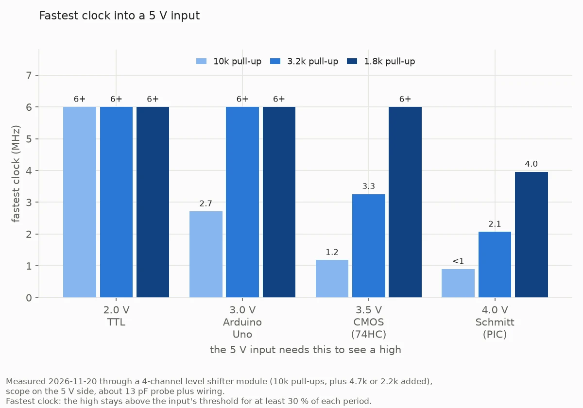
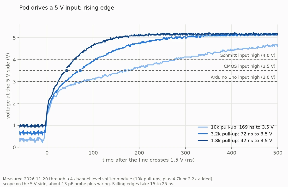
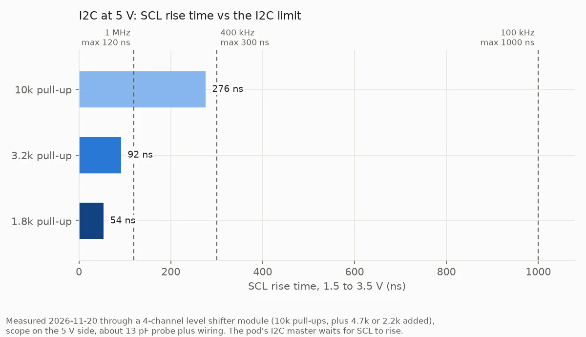
In the graphs, 3.2k is the module with 4.7k added, and 1.8k the module with 2.2k added.
Check your device
- Look up VIH (input high voltage) in the datasheet of the chip your signal goes into. At 5 V, "0.7 VCC" is 3.5 V, "0.6 VCC" is 3.0 V, and a TTL input is 2.0 V. Find that voltage in the rising-edge graph to see how long the line takes to get there.
- For I2C, check every device on the bus, and compare the SCL rise time with the limit for your speed: 1000 ns at 100 kHz, 300 ns at 400 kHz, 120 ns at 1 MHz.
- Also check VIL (input low voltage). An added pull-up raises the low the pod drives: about 0.4 V with the module alone, 0.7 V with 4.7k added, 1.0 V with 2.2k added. TTL inputs need under 0.8 V.
- Pull-ups already on your board add to the module's.
Limits
- Four channels per module. Use two modules for more.
- Digital signals only: no analog, and no current from a high (LEDs, relays need a driver).
- Every line idles high: a pin nobody drives reads high on both sides.
- Faster than the table: use a level shifter with a direction pin, or the 5 V I/O of the digital board v3r4.